Adblocker Detected

We always struggled to serve you with the best online calculations, thus, there's a humble request to either disable the AD blocker or go with premium plans to use the AD-Free version for calculators.
Disable your Adblocker and refresh your web page 😊
How Was Your Calculator Experience? ![]()

We'd Welcome your Feedback
Thank you for visiting our website. You have been selected to participate in a brief customer satisfaction survey to let us know how we can improve your experience
No, Thanks
Table of Content
The transformer calculator finds the primary and secondary full load currents (Amps) and voltages of single and 3-phase transformers. It can function to make calculations for both ideal and real transformers and identify their types based on the turns ratio.
Moreover, the tool also helps you estimate EMF & different transmission losses including
A transformer operates to deliver current from one AC circuit to one or more AC circuits. This component works according to Faraday’s Law of Electromagnetic Induction to either step up or down the voltage.
Transformer calculator considers the following equations that help you analyze a mathematical model of the transformer.
\(V_p = N_p / N_s × V_s\)
Where:
\(I_s=I_p*\dfrac{N_p}{N_s}\)
\(Full-Load Current (Amps)= kVA × 1000 / V\)
\(Full-Load Current (Amps) = kVA × 1000 / (1.732 × V)\)
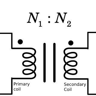
\(Turns Ratio = N_1 / N_2 = V_1 / V_2 = I_2 / I_1\)
Consider a single phase transformer of size about 56kVA. Its primary voltage is 350 volts and secondary voltage is almost 120 volts. Considering the transformer to be the ideal one, calculate the turns ratio and full load current range.
As the transformer is supposed to be ideal one:
Turns Ratio = N1 / N2 = V1 / V2 = (350 / 76) = 4.60
Determining the full load currents:
\(Primary Full-Load Current (Amps)= kVA × 1000 / V\)
\(Primary Full-Load Current (Amps)= 56 × 1000 / 350\)
\(Primary Full-Load Current (Amps)= 56 × 2.857\)
\(Primary Full-Load Current (Amps)= 159.992\)
\(Secondary Full-Load Current (Amps)= kVA × 1000 / V\)
\(Secondary Full-Load Current (Amps)= 56 × 1000 / 120\)
\(Secondary Full-Load Current (Amps)= 56 × 8.333\)
\(Secondary Full-Load Current (Amps)= 466.648\)
Related: Do not forget to calculate Voltage Drops and Amperage across different circuits while analyzing the functionality of a transformer.
To size a transformer effectively, you can use the given equation. All you need to simply multiply the amperes with the secondary output voltage.
Mathematically:
(VA) = Secondary Voltage * Required Current
Important: We do not recommend loading a transformer above 80% of its KVA rating. To find the minimum KVA rating needed, divide the calculated KVA by a factor of 0.8. All values should be reviewed and confirmed by an electrician or electrical engineer.
In a transformer, a rectifier behaves as a device that converts the AC into a high DC. This direct amperage is further used for different chemical processes, including
Power factor is the basic difference between kW and kVA. Where the kW is the power of the real transformer, the kVA is considered the power factor of the apparent transformer.
A 150 Kva transformer can handle primary voltage up to 480 V and secondary voltage up to 120/280V. The equivalent current rating for the voltage os about 400 Amps – CU.
| KVA | 120V | 208V | 240V | 277V | 480V | 600V |
| .25 | 1.2 | 1. | 0.9 | 0.5 | 0.4 | |
| .50 | 4.2 | 2.4 | 2.1 | 1.8 | 1.0 | 0.8 |
| .75 | 6.3 | 3.6 | 3.1 | 2.7 | 1.6 | 1.3 |
| 1 | 8.3 | 4.8 | 4.2 | 3.6 | 2.1 | 1.7 |
| 1.5 | 12.5 | 7.2 | 6.2 | 5.4 | 3.1 | 2.5 |
| 2 | 16.7 | 9.6 | 8.3 | 7.2 | 4.2 | 3.3 |
| 3 | 25 | 14.4 | 12.5 | 10.8 | 6.2 | 5 |
| 5 | 41 | 24 | 20.8 | 18 | 10.4 | 8.3 |
| 7.5 | 62 | 36 | 31 | 27 | 15.6 | 12.5 |
| 10 | 83 | 48 | 41 | 36 | 20.8 | 16.7 |
| 15 | 125 | 72 | 62 | 54 | 31 | 25 |
| 25 | 206 | 120 | 104 | 90 | 52 | 41 |
| 37.5 | 312 | 180 | 156 | 135 | 76 | 62 |
| 50 | 416 | 240 | 208 | 180 | 104 | 83 |
| 75 | 625 | 340 | 312 | 270 | 156 | 125 |
| 100 | 833 | 480 | 416 | 361 | 208 | 166 |
| 167 | 1391 | 803 | 695 | 603 | 347 | 278 |
| KVA | 208V | 240V | 480V | 600V |
| 3 | 8.3 | 7.2 | 3.6 | 2.9 |
| 6 | 16.6 | 14.4 | 7.2 | 5.8 |
| 9 | 25 | 21.6 | 10.8 | 8.6 |
| 15 | 41.7 | 36.1 | 18.0 | 14.4 |
| 30 | 83.4 | 72.3 | 36.1 | 28.9 |
| 45 | 124 | 108 | 54.2 | 43.4 |
| 75 | 208 | 180 | 90 | 72 |
| 112.5 | 312 | 270 | 135 | 108 |
| 150 | 416 | 360 | 180 | 144 |
| 225 | 624 | 541 | 270 | 216 |
| 300 | 832 | 721 | 360 | 288 |
| 500 | 1387 | 1202 | 601 | 481 |
| 750 | 2084 | 1806 | 903 | 723 |
| 1000 | 2779 | 2408 | 1204 | 963 |
| KVA | Insulation | |||
| 1 Phase | 3 Phase | NEMA Class | Temperature Class |
Temperature Rise |
| 0.25-25 | 3-15 | F | 180° C | 115° C |
| 15-167 | 15-1000 | H | 220° C | 150° C |
Get the ease of calculating anything from the source of calculator online
Powered By:

Other Website:


Email us at
We are Located at
71-75 Shelton Street, Covent Garden London
Follow Us
© Copyrights 2024 by Calculator-online.net