Adblocker Detected

We always struggled to serve you with the best online calculations, thus, there's a humble request to either disable the AD blocker or go with premium plans to use the AD-Free version for calculators.
Disable your Adblocker and refresh your web page 😊
How Was Your Calculator Experience? ![]()

We'd Welcome your Feedback
Thank you for visiting our website. You have been selected to participate in a brief customer satisfaction survey to let us know how we can improve your experience
No, Thanks
Table of Content
Calculate the overall drop in voltage for DC and AC circuits with the voltage drop calculator. The tool uses the NEC and Wire Resistance equations for power loss across a load connected in a single-phase and three-phase supply system and tells you the actual potential fall in the whole circuit.
In addition to that, you may also get the wire cross-sectional area, resistance, and voltage across terminals with the calculator.
“It is the overall loss of the voltage due to the internal impedance of the circuit”
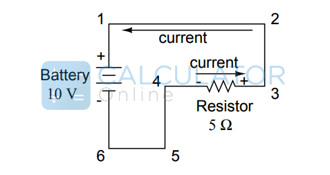
In the above figure, we have a potential voltage applied to a circuit network containing only a resistance. Now when the current passes through the resistance, there will be ampacity and drop in voltage from one end to the other end of the resistor. This drop can be instantly determined by using the voltage calculator above.
According to the IEEE (Institute of Electrical and Electronics Engineers), there are two types of voltage drop.
A positive drop occurs when the electronic current flows through the circuit.
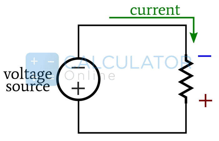
This voltage drop usually occurs in a circuit when there is a conventional current flowing through it.
\(V_{drop\left(V\right)} = I_{cable\left(A\right)} * R_{wire\left(ohms\right)}\)
\(V_{drop\left(V\right)} = I_{wire\left(A\right)} * \left(2 * L_{\left(ft\right)} * \frac{R_{wire\left(\frac{Ω}{kft}\right)}}{1000_{\left(\frac{ft}{kft}\right)}}\right)\)
\(V_{drop\left(V\right)} = I_{wire\left(A\right)} * R_{wire\left(Ω\right)}\)
\(V_{drop\left(V\right)} = I_{wire\left(A\right)} * \left(2 * L_{\left(m\right)} * \frac{R_{cable\left(\frac{ohms}{km}\right)}}{1000_{\left(\frac{m}{km}\right)}}\right)\)
\(V_{drop\left(V\right)} = \sqrt{3} * I_{wire\left(A\right)} * R_{wire\left(Ω\right)}\)
\(V_{drop\left(V\right)} = 1.732 * I_{wire\left(A\right)} * \left(L_{\left(ft\right)} * \frac{R_{wire\left(\frac{Ω}{kft}\right)}}{1000_{\left(\frac{ft}{kft}\right)}}\right)\)
\(V_{drop\left(V\right)} = \sqrt{3} * I_{wire\left(A\right)} * R_{wire\left(Ω\right)}\)
\(V_{drop\left(V\right)} = 1.732 * I_{wire\left(A\right)} * \left(L_{\left(m\right)} * \frac{R_{wire\left(\frac{ohms}{km}\right)}}{1000_{\left(\frac{m}{km}\right)}}\right)\)
Whatever the phase is, the calculator will take a couple of seconds to display the actual loss in the voltage transmission.
For a cable having a diameter in inches and n gauges:
\(d_{n\left(in\right)} = 0.005 inches * 92^{\frac{\left(36-n\right)}{39}}\)
\(d_{n\left(mm\right)} = 0.127 mm * 92^{\frac{\left(36-n\right)}{39}}\)
\(A_{n\left(kcmil\right)} = 1000 * d_{n}^{2} = 0.025 in^{2} * 92^{\frac{\left(36-n\right)}{19.5}}\)
\(A_{n\left(in^{2}\right)} = \left(\frac{\pi}{4}\right) * d_{n}^{2} = 0.000019635 in^{2} * 92^{\frac{\left(36-n\right)}{19.5}}\)
\(A_{n\left(mm^{2}\right)} = \left(\frac{\pi}{4}\right) * d_{n}^{2} = 0.000019635 mm^{2} * 92^{\frac{\left(36-n\right)}{19.5}}\)
\(R_{n\left(\frac{Ω}{kft}\right)} = 0.3048 * 10^{9} * \frac{ρ\left(Ω.m\right)}{25.4^{2} * A_{n\left(in^{2}\right)}}\)
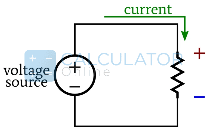
When the potential at the end of the wire gets higher than the potential at the start, then it gives rise to the potential voltage drop.
The distance is directly proportional to the resistance and when the resistance increases, the Voltage drop will also get maximum.
You must keep checking the drop with the calculator to analyze better.
The maximum voltage loss calculation that could be tolerable between a feeder conductor to the farthest load connected in series or parallel must not exceed the value of 5%.
| AWG | Diameter | Turns of cable | Area | Copper resistance | ||||
| inch | mm | per inch | per cm | kcmil | mm2 | Ω/km | Ω/1000ft | |
| 0000 (4/0) | 0.4600 | 11.684 | 2.17 | 0.856 | 212 | 107 | 0.1608 | 0.04901 |
| 000 (3/0) | 0.4096 | 10.404 | 2.44 | 0.961 | 168 | 85.0 | 0.2028 | 0.06180 |
| 00 (2/0) | 0.3648 | 9.266 | 2.74 | 1.08 | 133 | 67.4 | 0.2557 | 0.07793 |
| 0 (1/0) | 0.3249 | 8.252 | 3.08 | 1.21 | 106 | 53.5 | 0.3224 | 0.09827 |
| 1 | 0.2893 | 7.348 | 3.46 | 1.36 | 83.7 | 42.4 | 0.4066 | 0.1239 |
| 2 | 0.2576 | 6.544 | 3.88 | 1.53 | 66.4 | 33.6 | 0.5127 | 0.1563 |
| 3 | 0.2294 | 5.827 | 4.36 | 1.72 | 52.6 | 26.7 | 0.6465 | 0.1970 |
| 4 | 0.2043 | 5.189 | 4.89 | 1.93 | 41.7 | 21.2 | 0.8152 | 0.2485 |
| 5 | 0.1819 | 4.621 | 5.50 | 2.16 | 33.1 | 16.8 | 1.028 | 0.3133 |
| 6 | 0.1620 | 4.115 | 6.17 | 2.43 | 26.3 | 13.3 | 1.296 | 0.3951 |
| 7 | 0.1443 | 3.665 | 6.93 | 2.73 | 20.8 | 10.5 | 1.634 | 0.4982 |
| 8 | 0.1285 | 3.264 | 7.78 | 3.06 | 16.5 | 8.37 | 2.061 | 0.6282 |
| 9 | 0.1144 | 2.906 | 8.74 | 3.44 | 13.1 | 6.63 | 2.599 | 0.7921 |
| 10 | 0.1019 | 2.588 | 9.81 | 3.86 | 10.4 | 5.26 | 3.277 | 0.9989 |
| 11 | 0.0907 | 2.305 | 11.0 | 4.34 | 8.23 | 4.17 | 4.132 | 1.260 |
| 12 | 0.0808 | 2.053 | 12.4 | 4.87 | 6.53 | 3.31 | 5.211 | 1.588 |
| 13 | 0.0720 | 1.828 | 13.9 | 5.47 | 5.18 | 2.62 | 6.571 | 2.003 |
| 14 | 0.0641 | 1.628 | 15.6 | 6.14 | 4.11 | 2.08 | 8.286 | 2.525 |
| 15 | 0.0571 | 1.450 | 17.5 | 6.90 | 3.26 | 1.65 | 10.45 | 3.184 |
| 16 | 0.0508 | 1.291 | 19.7 | 7.75 | 2.58 | 1.31 | 13.17 | 4.016 |
| 17 | 0.0453 | 1.150 | 22.1 | 8.70 | 2.05 | 1.04 | 16.61 | 5.064 |
| 18 | 0.0403 | 1.024 | 24.8 | 9.77 | 1.62 | 0.823 | 20.95 | 6.385 |
| 19 | 0.0359 | 0.912 | 27.9 | 11.0 | 1.29 | 0.653 | 26.42 | 8.051 |
| 20 | 0.0320 | 0.812 | 31.3 | 12.3 | 1.02 | 0.518 | 33.31 | 10.15 |
| 21 | 0.0285 | 0.723 | 35.1 | 13.8 | 0.810 | 0.410 | 42.00 | 12.80 |
| 22 | 0.0253 | 0.644 | 39.5 | 15.5 | 0.642 | 0.326 | 52.96 | 16.14 |
| 23 | 0.0226 | 0.573 | 44.3 | 17.4 | 0.509 | 0.258 | 66.79 | 20.36 |
| 24 | 0.0201 | 0.511 | 49.7 | 19.6 | 0.404 | 0.205 | 84.22 | 25.67 |
| 25 | 0.0179 | 0.455 | 55.9 | 22.0 | 0.320 | 0.162 | 106.2 | 32.37 |
| 26 | 0.0159 | 0.405 | 62.7 | 24.7 | 0.254 | 0.129 | 133.9 | 40.81 |
| 27 | 0.0142 | 0.361 | 70.4 | 27.7 | 0.202 | 0.102 | 168.9 | 51.47 |
| 28 | 0.0126 | 0.321 | 79.1 | 31.1 | 0.160 | 0.0810 | 212.9 | 64.90 |
| 29 | 0.0113 | 0.286 | 88.8 | 35.0 | 0.127 | 0.0642 | 268.5 | 81.84 |
| 30 | 0.0100 | 0.255 | 99.7 | 39.3 | 0.101 | 0.0509 | 338.6 | 103.2 |
| 31 | 0.00893 | 0.227 | 112 | 44.1 | 0.0797 | 0.0404 | 426.9 | 130.1 |
| 32 | 0.00795 | 0.202 | 126 | 49.5 | 0.0632 | 0.0320 | 538.3 | 164.1 |
| 33 | 0.00708 | 0.180 | 141 | 55.6 | 0.0501 | 0.0254 | 678.8 | 206.9 |
| 34 | 0.00630 | 0.160 | 159 | 62.4 | 0.0398 | 0.0201 | 856.0 | 260.9 |
| 35 | 0.00561 | 0.143 | 178 | 70.1 | 0.0315 | 0.0160 | 1079 | 329.0 |
| 36 | 0.00500 | 0.127 | 200 | 78.7 | 0.0250 | 0.0127 | 1361 | 414.8 |
| 37 | 0.00445 | 0.113 | 225 | 88.4 | 0.0198 | 0.0100 | 1716 | 523.1 |
| 38 | 0.00397 | 0.101 | 252 | 99.3 | 0.0157 | 0.00797 | 2164 | 659.6 |
| 39 | 0.00353 | 0.0897 | 283 | 111 | 0.0125 | 0.00632 | 2729 | 831.8 |
| 40 | 0.00314 | 0.0799 | 318 | 125 | 0.00989 | 0.00501 | 3441 | 1049 |
Get the ease of calculating anything from the source of calculator online
Powered By:

Other Website:


Email us at
We are Located at
71-75 Shelton Street, Covent Garden London
Follow Us
© Copyrights 2024 by Calculator-online.net